

 TM 11-2504 ·Army ·1943
Public Address Sets PA-5 and PA-5-A
PUBLIC ADDRESS SETS PA-5 AND PA-5-A d. Corrective measures. The corrective measures listed are those that the operator can make without turning the equipment in for repairs. References in the table to paragraphs 39 through 41 indi cate… TC 3-12.2.4.1 ·Army ·2024
Analytic Support to Defensive Cyberspace Operations
17 January 2024 TC 3-12.2.4.1 v Acknowledgements Reference style. The copyright owners listed here have granted permission to reproduce material from their works. The Source Notes lists other sources of quotations and photographs. MITRE… NAVEDTRA 14224 ·Navy ·1997
Information Systems Technician Training Series Module 3: Network Communications
By enrolling in this self-study course, you have demonstrated a desire to improve yourself and the Navy. Remember, however, this self-study course is only one part of the total Navy training program. Practical experience, schools, selected… TM 11-264 ·Army ·1950
Radio Set AN/GRC-26
Covers the description, operation, and maintenance of Radio Set AN/GRC-26, including Radio Transmitter T-213/GRC-26. TM 11-273 ·Army ·1941
Radio Sets SCR-193-A, SCR-193-B, SCR-193-C, SCR-193-D, and SCR-193-E
TM 11-273 RADIO SETS SCR-193-A, ETC. 1-4 1. Purpose.— Radio sets SCE-193-A, SCR-193-B, SCR-193-C, SCR-193-D, and SCR-193-E are designed for installation in vehicles for the purpose of providing intervehicular communication whether the… FM 11-8 ·Army ·1957
Field Radio Relay Techniques
Section 1. GENERAL 1. Purpose and Scope The purpose of this manual is to provide tactical and certain technical information for staff planners and those technicians within the field army concerned with the installation and operation of… FM 11-21 ·Army ·1961
Tactical Signal Communication Systems Army, Corp
CHAPTER 2 SIGNAL COMMUNICATION SYSTEMS Section I. GENERAL 4. Basic Considerations a. Tactical commanders continually stress dispersion, mobility, and flexibility in the employment of tactical units. However, dispersion, mobility, and… TM 11-6625-274 ·Army ·1960
Test Sets, Electron Tube TV-7/U, TV-7A/U, TV-7B/U, and TV-7D/U
Field and depot maintenance manual for Electron Tube Test Sets TV-7/U, TV-7A/U, TV-7B/U, and TV-7D/U, covering theory of operation, troubleshooting, repair, and alignment. TM 11-2057A ·Army ·1952
Test Set TS-27B/TSM
1. Scope. This appendix lists only basic issue items required by the crew/operator for installation, operation, and maintenance of Test Set TS-27B/TSM. 2. General. This Basic Issue Items and Items Troop Installed or Authorized List is… ATP 6-02.40 C1 ·Army ·2019
Techniques for Visual Information Operations
ATP 6-02.40 28 April 2021 Acknowledgements Assorted photos from https://www.dvidshub.net/ are courtesy of the United States Defense Visual Information Distribution Service. Assorted photos from https://catalog.archives.gov/ are courtesy of… TM 11-1257 ·Army ·1953
Signal Generator AN/URM-48
WARNING HIGH VOLTAGE is used in the operation of this equipment. DEATH ON CONTACT may result if operating personnel fail to observe safety precautions. TM 11-2258 ·Army ·1947
Facsimile Sets AN/TXC-1, -1A, and -1B
WARNING HIGH VOLTAGE is used in the operation of this equipment. DEATH ON CONTACT may result if personnel fail to observe safety precautions. vii FM 3-36 ·Army ·2009
Electronic Warfare in Operations
FM 3-36 provides Army doctrine for electronic warfare (EW) planning, preparation, execution, and assessment in support of full spectrum operations. Users of FM 3-36 must be familiar with full spectrum operations established in FM 3-0; the… FM 100-32 ·Army ·1975
Tactical Electronic Warfare TEST
FM 100-32 (TEST) CHAPTER 1 GENERAL 1-1. Purpose This manual provides guidance to commanders and staff officers in the tactical aspects of elec- tronic warfare employment in combat opera- tions. It has been purposely written without… TM 11-800 ·Army ·1942
Radio Transmitters BC-191-A, BC-191-B, BC-191-C, BC-191-D, BC-191-E, and BC-AA-191
TM 11-800 1 SIGNAL CORPS CHAPTER 1 GENERAL Paragraph Differences in models 1 1. Differences in models.—a. Radio transmitters BC-191-(*) and BC-AA-191 with their associated equipment are designed for use as component parts of radio sets… TM 11-238 ·Army ·1942
Radio Sets SCR-194 and SCR-195 and Auxiliary Equipment
RADIO SETS seR- I'" M.-o eCR- U6 TJ( 11-238 , Then! i no operating diffel''ence between the two sets. The general design and construction are identical except that, the frequency band of the SOR- 194 is covered by two interchangeable… TM 11-5011 ·Army ·1949
Radio Receiver R-206A/PR
Covers the description, operation, and maintenance of Radio Receiver R-206A/PR, including theory, trouble-shooting, and alignment. TM 11-4062 ·Army ·1946
Radio Transmitter T-55/MRQ-2 (Repair Instructions)
eee er AR I MOE N Te TR CA NAC ACL MOAN: UO Ak Pa ee be 0-6: 2 RADIO TRANSMITTER T-55/MRQ-2 REPAIR INSTRUCTIONS WAR DEPARTMENT ° TAN U AR YY 19.66 WARNING: The material forming the subject matter of this manual is the property of the… TM 11-704 ·Army ·1951
Auxiliary Interphone Equipment AN/VIA-1
Covers Auxiliary Interphone Equipment AN/VIA-1. TM 11-939 ·Army ·1943
Power Unit PE-182
WAR DEPARTMENT TECHNICAL MANUAL fa Gales Gey AE I fone This manual supersedes TM 11-939, December 1943 POWER UNIT PE-182 WAR DEPARTMENT 4 OCTOBER 1944 RESTRICTED. pissEMINATION OF RESTRICTED MATTER. The information contained in restricted…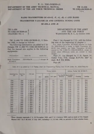 TM 11-826 ·Army ·1960
Radio Transmitters BC-610-E, -F, -G, -H, -I and Radio Transmitter T-213/GRC-26 and Antenna Tuning Units BC-939-A and -B
Covers Radio Transmitters BC-610-E through -I, Radio Transmitter T-213/GRC-26, and Antenna Tuning Units BC-939-A and -B.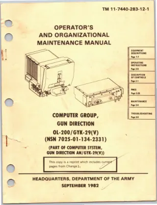 TM 11-7440-283-12-1 ·Army ·1982
Operator's and Organizational Maintenance Manual: Computer Group, Gun Direction OL-200/GYK-29(V)
Dangerous rf voltages exist around antennas and antenna terminals during transmission. Protect yourself by knowing the safety procedures in TB SIG 291. *DO NOT allow the antennas to touch powerlines. Tie them down before moving. *DO NOT… TM 11-2146 ·Army ·1954
Manual Telephone Central Office AN/TTC-7
Note. (Added) The basic manual covers Manual Telephone Switchboard SB-249/TTC, serial numbers 1 through 321, and Trunk Relay Telephone Circuit TA-226/TTC, serial numbers 1 through 107. Manual Telephone Switchboard SB-249/TTC, serial… TM 11-655 ·Army ·1954
Fundamentals of Telegraphy (Teletypewriter)
Section I . DEVELOPMENT AND DESCRIPTION 1. General Early methods of communication seem prim itive when compared with present day systems. These early methods included signaling audibly by gunfire, drums, and other loud noises, and visually… TM 11-2535A ·Army ·1952
Meter Test Equipment AN/GSM-1B
Section I. GENERAL 1. Scope a. These instructions are published for the in- formation and guidance of the personnel to whom this equipment is issued. ‘They contain a descrip- tion of the equipment; information on operation, organizational… TM 11-346 ·Army ·1944
Test Sets I-61-A, I-61-B, and I-61-C
LIST OF ILLUSTRATIONS Fig. No. Title Page 20. Schematic diagram for measuring transmission through a switchboard cord circuit 23 21. Schematic diagram for measuring transmission through a switchboard line or trunk circuit 23 22. Schematic… TM 11-432 ·Army ·1942
Code Practice Equipment
TECHNICAL MANUAL CODE PRACTICE EQUIPMENT TJI( 11-432 '0. 'lJyAR DEPARTMENT, No. 2 W D. 0.,,20 A:prll 19H. TM 11--482, 2 February 1942, is changed as follows: MPENDlJ[ III (ADDED) EMERGENCY CODE PRACTICE EQUIPMENT 1. General.-In order that… FM 6-02-40 ·Army ·2009
Visual Information Operations
Unless this publication states otherwise, masculine nouns and pronouns do not refer exclusively to men. TM 11-851 ·Army ·1954
Supplement to TM 11-851
2. i RTAL PHASING : TM 851-101 Figure 10.1. Radio Receiver R-620/FRR, front view. 13.1. Description of Radio Receiver R- 620/FRR a. Radio Receiver R-620/FRR (fig. 10.1 and 10.2) is the rack mounting type (par. 8a). The receiver… TM 11-344 ·Army ·1946