

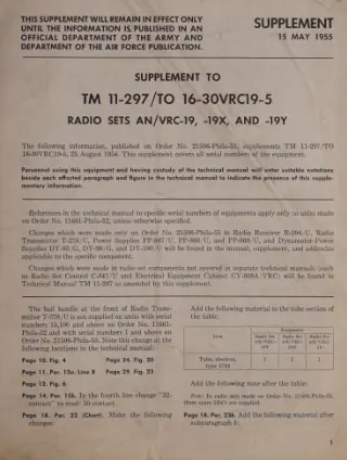
 TM 11-297 ·Army ·1955
Supplement to TM 11-297/ TO 16-30VRC19-5 Radio Sets AN/VRC-19, -19X, and -19Y
Supplement covering Radio Sets AN/VRC-19, -19X, and -19Y, with changes and supplementary information to the basic technical manual. TM 11-300 ·Army ·1944
Frequency Meter Sets SCR-211
To prevent the enemy from using or salvaging this equipment for his benefit. WHEN—When ordered by your commander. HOW — 1. Smash—Use sledges, axes, handaxes, pickaxes, hammers, crow- bars, heavy tools, etc. 2, Cut—Use axes, handaxes,… TM 11-302 ·Army ·1941
Charging Set SCR-169
TM: n-302 C 1 TECHNICAL MANUAL, 10y4. (Added.) Power units PE-HF-43 and PE-HG-43.— These units are identical with power units PE-HD—13 and PEHE-43. All information in paragraphs 1 to 10 inclusive pertaining to power units PE-HD-43 and… TM 11-303 ·Army ·1944
Test Sets I-56-C, -D, -H, -J
TM 11-303 Pars. 1-3 This manual supersedes War Department Training Circular 69, 19 May 1943 SECTION I DESCRIPTION 1. PURPOSE. Test Sets I-56-C, I-56-D, I-56-H and 1-56 J, referred to in this text as Test Set 1-56- (*), are electrical… TM 11-306 ·Army ·1943
Maintenance Equipments ME-13-A, B, C, and D
5. Adapter RS-259 This adapter is used for aligning Radio Sets SCR-509-(*), SCR-510- (*), and SCR-610-C*). It plugs into the transmitter Battery BA-39, thereby placing a 500-ohm, 5-watt resistance in series with the highvoltage (h-v) lead.… TM 11-307 ·Army ·1943
Signal Generators I-72-G and I-72-H
Covers the description, functioning, operation, and maintenance of Signal Generators I-72-G and I-72-H. TM 11-308 ·Army ·1944
Remote Control Unit RM-29-(*)
Covers the description, installation, operation, functioning, and maintenance of Remote Control Unit RM-29. TM 11-310 ·Army ·1943
Schematic Diagrams for Maintenance of Ground Radio Communication Sets
RESTRICTED TM 11-310 SCHEMATIC DIAGRAMS FOR MAINTENANCE OF GROUND RADIO COMMUNICATION SETS This manual contains a condensation of information for the maintenance of Signal Corps ground radio communication sets. It is presented as a… TM 11-312 ·Army ·1943
Remote Control Equipment RC-47-A, B, C, D, and G
C, nsny of itter ermit ote trol mitter e point pairs units, attery sed for m the he revers may switch. s th field es under r. The signating equipnd all equipM-13-(*) refers RM-13-D, and nd to those of the example, Control 55-D are comn —… TM 11-313 ·Army ·1943
Allen Model E-2 Unitron Rectifier
capture of this equipment, O PART OF IT CAN MY, BURN ALL cts are readily e, oil, paper, or tes and circuit ent-boards. means and meters. gas, oil, and water er rotating, moving phones, microainers, etc. or dispose of it in ULD NOT BE A-C… TM 11-317 ·Army ·1943
Signal Generator I-208
WAR DEPARTMENT Washington 25, D. C. 28 Aug 1943 This Technical Manual is furnished for the information and guidance of all concerned. RESTRICTED Dissemination of restricted matter.— The information con tained in restricted documents and… TM 11-318 ·Army ·1943
Alignment Equipment ME-73
Covers Alignment Equipment ME-73 and procedures for aligning Radio Sets SCR-509/510 and SCR-609/610 series. TM 11-321 ·Army ·1943
Test Set I-56-E
11-321 SIGNAL CORPS een nen rest aae Figure 1 View showing Test Set I-56-E complete with each unit in place in carrying case. TM 11-330 ·Army ·1944
Switchboards BD-71, BD-72, BD-72-A, and BD-72-B
TECHNICAL SWITCHBOARDS BD-71, BD-72, AJtfD Changes! DEPAETMENT, No. 1 J D. C., December 1944. TM 11-330, 29 October 1943, is changed as follows : 11.1. GENERAL (Added). The outbreak of gas war fare -should not interfere with the continuity… TM 11-331 ·Army ·1931
Switchboard BD-14
Covers the description, installation, operation, function of parts, and maintenance of Switchboard BD-14. TM 11-332 ·Army ·1942
Telephone Central Office Set TC-4
TM 11-332 ci TECHNICAL MANU TELEPHONE CENTRAL OFFfCETSET TC-4 'FICF/SI CHANGES 1 W JUfcsljEPARTMENT, /'No/l J TM. 11-332, June 1, 1942, is 6. Switchboard operatic * * * /. Grouping key. * * * (3) The A and B leads are commonto Ml cord… TM 11-333 ·Army ·1945
Telephones EE-8, EE-8-A and EE-8-B
WAR DEPARTMENT TECHNICAL MANUAL . "I. A j f hft *.' " , TELEPHONES , EE-8, EE-8-A AND EE-8-B WARNING: The material forming the subject matter of this manual is the property of the United States Government and it is printed and distributed… TM 11-334 ·Army ·1946
Timing and Telephone Set ML-110
Section I. DESCRIPTION OF TIMING AND TELEPHONE SET ML-110 1. General a. Timing and Telephone Set ML-110 consists of Time Interval Unit ML-138 and associated equipment. The timing and tele phone set is designed as an aid in making… TM 11-336 ·Army ·1943
Telephone Central Office Set TC-12
TM 11-336 V3 TECHNICAL M TELEPHONE CENTRAL OFFI / I "*""" • - CHANGES! / *OWAB DEPARTMENT, No. 1 WASHINGTON, May 12, 1943. TM 11-336, January 18, 1943, is changed as follows : APPENDIX (ADDED) MOBILE TELEPHONE CENTRAL OFFICE FOR DIVISIONS… TM 11-338 ·Army ·1944
Telephone Central Office Set TC-10
Covers the description, installation, operation, and maintenance of Telephone Central Office Set TC-10, including Switchboard BD-110. TM 11-340 ·Army ·1943
Telephone Central Office Set TC-2
11-340 MANUAL TELEPHONE CENTRAL OFFICE SET TC-2 CHANGES! WAR DEPARTMENT, 1 J WASHimiiua 25, R C., 12 November 1943. TM 11-340, 19 October 1942, is changed as follows: 2. Description. &. Cabinet BE-79 (main distributing frame) (fig. 2). —… TM 11-344 ·Army ·1946
Converter M-222
Covers the description, installation, and operation of Converter M-222. TM 11-345 ·Army ·1942
Cabinet BE-70-( ) (Wire Chief's Testing)
Table of resistance versus voltmeter reading for various test battery voltages. Voltmeter, 100,000 ohms (voltmeter not shunted) ' Voltmeter• 199.6 ohms (VM SHUNT key operated) ' Voltmeter reading (Maximum test battery voltage) (Maximum… TM 11-346 ·Army ·1944
Test Sets I-61-A, I-61-B, and I-61-C
LIST OF ILLUSTRATIONS Fig. No. Title Page 20. Schematic diagram for measuring transmission through a switchboard cord circuit 23 21. Schematic diagram for measuring transmission through a switchboard line or trunk circuit 23 22. Schematic… TM 11-351 ·Army ·1945
Telegraph Sets TG-5, TG-5-A, and TG-5-B
 TM 11-356 ·Army ·1943
Radio Teletype Terminal Equipment AN/FGC-1 or AN/FGC-1X
INTRODUCTION. a. The Radio Teletype Terminal Equipment AN/FGC1 or AN/FGC-1X forms part of a radio-telegraph system, the receiving circuit being designed to receive signals alternately from one or two radio transmitters at moderate… TM 11-359 ·Army ·1943
Line Unit BE-77-A and Line Unit BE-77
Covers Line Units BE-77, BE-77-A, and BE-77-B, including operation and maintenance. TM 11-360 ·Army ·1941
Reel Units RL-26 and RL-26-A
TM 11-360 REEL UNITS RL-26 AND RL-26-A 1-2 mounted, the units can also be operated in temporary fixed positions 011 the ground. 2. Characteristics. —a. RL-26.—All component parts of the reel unit RL-26 are assembled on a skid frame which… TM 11-361 ·Army ·1941
Test Sets EE-65 and EE-65-A
Covers Test Sets EE-65 and EE-65-A, used for measuring wire and cable resistance. TM 11-362 ·Army ·1941