

 TM 11-689 ·Army ·1956
Radio Set AN/TRC-29 and Radio Repeater Set AN/TRC-39
Covers Radio Set AN/TRC-29 and Radio Repeater Set AN/TRC-39, including installation, adjustment, and operation of the radio relay system. TM 11-6940-205-15 ·Army ·1960
Operator's, Organizational, Field and Depot Maintenance Manual: Trainer, Radar AN/ULT-T2
in the 7.36- to 10.0-kme frequency range. The horn antenna is fed by a section of waveguide with inside dimensions that are slightly smaller than the standard X-band waveguide. The waveguide is terminated at one end with a… TM 11-700 ·Army ·1942
Interphone Equipments RC-53 and RC-53-A
TM 11-700 RESTRICTED TECHNICAL MANUAL! WAR DEPARTMENT No. 11-700 J WASHINGTON, February 2, 1942. INTERPHONE EQUIPMENTS RC-53 AND RC-53-A Prepared under direction of the Chief Signal Officer Paragraphs SECTION I. Description . 1-5 II.… TM 11-702 ·Army ·1944
Interphone Equipment RC-99
Demolish all panels, castings, switch-and instrument-boards . 3. Destroy all controls, switches, relays, connecting means and meters. 4. Rip out all wiring in electrical equipment. Smash gas and oil lines, and water cooling systems in… TM 11-704 ·Army ·1951
Auxiliary Interphone Equipment AN/VIA-1
Covers Auxiliary Interphone Equipment AN/VIA-1. TM 11-7440 ·Army ·1985
Hewlett-Packard Model 9845B Desktop Computer
B-1. Scope This appendix lists integral components of and basic issue tons for the Hewlett-Packard Model 9845B Desktop Computer to help you inventory items required for safe and efficient operation. B-2. General This Components of End Item…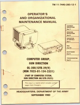 TM 11-7440-283-12-1 ·Army ·1982
Operator's and Organizational Maintenance Manual: Computer Group, Gun Direction OL-200/GYK-29(V)
Dangerous rf voltages exist around antennas and antenna terminals during transmission. Protect yourself by knowing the safety procedures in TB SIG 291. *DO NOT allow the antennas to touch powerlines. Tie them down before moving. *DO NOT… TM 11-800 ·Army ·1942
Radio Transmitters BC-191-A, BC-191-B, BC-191-C, BC-191-D, BC-191-E, and BC-AA-191
TM 11-800 1 SIGNAL CORPS CHAPTER 1 GENERAL Paragraph Differences in models 1 1. Differences in models.—a. Radio transmitters BC-191-(*) and BC-AA-191 with their associated equipment are designed for use as component parts of radio sets…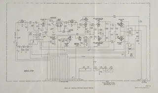 TM 11-806 ·Army ·2025
Tm 11-806
 TM 11-826 ·Army ·1960
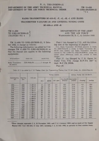
Radio Transmitters BC-610-E, -F, -G, -H, -I and Radio Transmitter T-213/GRC-26 and Antenna Tuning Units BC-939-A and -B
Covers Radio Transmitters BC-610-E through -I, Radio Transmitter T-213/GRC-26, and Antenna Tuning Units BC-939-A and -B. TM 11-830A ·Army ·1952
Radio Transmitting Set AN/SRT-1A
WARNING HIGH VOLTAGE is used in the operation of this equipment. DEATH ON CONTACT may result if operating personnel fail to observe safety precautions. vi TM 11-844 ·Army ·1954
Radio Transmitting Sets AN/SRT-13 and -13X
Section I. 1. Scope a. This technical manual contains necessary in- formation for the installation, operation, main- tenance, and repair of Radio Transmitting Set AN/SRT-13 (fig. 1) and Radio Transmitting Set AN/SRT-13X (fig. 2). In… TM 11-850 ·Army ·1944
Radio Receivers BC-312-(*), BC-312-(*)X, BC-342-(*), BC-314-(*), and BC-344-(*)
Covers Radio Receivers BC-312-(*), BC-312-(*)X, BC-342-(*), BC-314-(*), and BC-344-(*), including their installation, operation, and the differences between models. TM 11-851 ·Army ·1954
Supplement to TM 11-851
2. i RTAL PHASING : TM 851-101 Figure 10.1. Radio Receiver R-620/FRR, front view. 13.1. Description of Radio Receiver R- 620/FRR a. Radio Receiver R-620/FRR (fig. 10.1 and 10.2) is the rack mounting type (par. 8a). The receiver… TM 11-854 ·Army ·1952
Radio Receiver R-388/URR
AGO 3261A WARNING HIGH VOLTAGE is used in the operation of this equipment. DEATH ON CONTACT may result if operating personnel fail to observe safety precautions. TM 11-858 ·Army ·1954
Radio Receiver R-392/URR
Instruction book for Radio Receiver R-392/URR, covering its introduction, operation, and maintenance. TM 11-859 ·Army ·1944
Radio Set SCR-593-A
WAR DEPARTMI Washington, March 2, This Technical Manual, published by Galvin Mfg. Corp. on orde No. 5515-Chi-42 and 13370-Phila-43, is furnished for the informatic and guidance of all concerned. RESTRICTED NOTICE: —This document contains… TM 11-862 ·Army ·1942
Radio Set SCR-504-A (Direction Finding)
To prevent the enemy from using or salvaging this equip ment for his benefit. WHEN—When ordered by your commander or when you are in immediate danger of capture. HOW— 1. Smash —Use sledges, axes, hand-axes, pick-axes, ham mers, crowbars,… TM 11-866 ·Army ·1948
Radio Receivers BC-779-A, -B; BC-794-A, -B; BC-1004-B, -C, -D; and R-129/U (Hammarlund Super Pro Receiver)
WARNING HIGH VOLTAGE is used in the operation of this equipment. DEATH ON CONTACT may result if operating personnel fail to observe safety precautions. TM 11-867 ·Army ·1944
Radio Receiver BC-787-B
WAR DEPARTMENT TECHNICAL MANUAL TM 11-867 RADIO RECEIVER BC-787-B WAR DEPARTMENT 21 JULY 1944 RESTRICTED. DISSEMINATION OF RESTRICTED MATTER. The information contained in restricted documents and the essential characteristics of restricted… TM 11-873 ·Army ·1943
Radio Set SCR-614-A, Radio Receiver BC-969-A, Power Supply Unit RA-61-A
WAR DEPARTMENT TECHNICAL MANUAL TM 11-873 RESTRICTED RADIO SET SCR-614-A RADIO RECEIVER BC-969-A POWER SUPPLY UNIT RA-61-A This document contains information affecting the national defense of the United States within the meaning of the… TM 11-874 ·Army ·1944
Radio Receiver AN/GRR-2 (Hallicrafters Model SX-28-A)
C 1, TM 11-874. TO 16-30GRR2-5 TECHNICAL MANUAL RADIO RECEIVER AN/GRR-2 (HALLICRAFTERS MODEL SX-28-A) CHANGES DEPARTMENT OF THE ARMY No. 1 WasuinetTon 25, D.C., 15 April 1954 TM 11-874, 22 November 1944, is changed as follows: 10.1… TM 11-875 ·Army ·1950
Radio Receivers R-203/SR and R-203A/SR
The high voltage that is used in the operation of this equipment may cause a painful shock. Be careful not to contact the ship's ground and a voltage point in the set during servicing operations. TM 11-878 ·Army ·1945
Radio Receiver R-96/SR
Covers Radio Receiver R-96/SR, including its description, installation and operation, functioning of parts, and maintenance.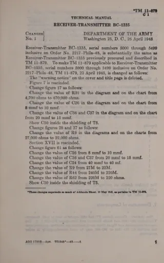 TM 11-879 ·Army ·1948
Receiver-Transmitter BC-1335
8. Unpacking, Uncrating, and Checking (Superseded) Unpack the receiver-transmitter carefully and inspect for possible damage during shipment (fig. 8). The receiver-transmitter is shipped with all tubes and crystals installed. To unpack,… TM 11-885 ·Army ·1946
Radio Receiver R-140/FSM-1: National HRO Series of Receivers
WARNING HIGH VOLTAGE is used in the operation of this equipment. DEATH ON CONTACT may result if operating personnel fail to observe safety precautions. Make certain that high voltage power supply capacitors are discharged before attempting… TM 11-896A ·Army ·1952
Radio Receiving Set AN/FRR-12X
Covers Radio Receiving Set AN/FRR-12X, including its description, operating instructions, and organizational maintenance. TM 11-897 ·Army ·1952
Radio Receiver R-274/FRR
WARNING HIGH VOLTAGE is used in the operation of this equipment. DEATH ON CONTACT may result if operating personnel fail to observe safety precautions. Be careful not to contact 175-volt connections or 115-volt a-c input connections when… TM 11-898 ·Army ·1956
Radio Receivers R-108/GRC, R-109/GRC, and R-110/GRC
Section GENERAL 1. Scope a. This technica] manual contains a description, ‘detailed theory of operation, and instructions for field maintenance and repair of Radio Receivers -R-108/GRC, R-109/GRC, and R-110/GRC (fig! 1). In addition, a… TM 11-899 ·Army ·1949