

 TM 11-5046 ·Army ·1951
Homing Beacon AN/CRN-12
WARNING HIGH VOLTAGE is used in the operation of this equipment. DEATH ON CONTACT may result if operating personnel fail to observe safety precautions. When working with the equipment, be extremely careful not to come in contact with… TM 11-5073 ·Army ·1956
Tower AB-216/U, Tower Section Set AB-298/U, Guy Kit MK-99/U, Accessory Kit MK-100/U, Guy Kit MK-101/U
Google This is a digital copy of a book that was preserved for generations on library shelves before it was carefully scanned by Google as part of a project to make the world's books discoverable online. It has survived long enough for the… TM 11-920 ·Army ·1940
Power Units PE-49-C, -D, -F, and -G and Motor Generator MG-37-A
Section I. DESCRIPTION 1. General a. Power Units PE-49-C, -D, -F, and -G and Motor Generator MG-37-A are compact, self-contained, light-weight, portable power generating sets, designed to supply continuous highand low-voltage direct… TM 11-5820-398-35 ·Army ·1963
Field and Depot Maintenance Manual : Radio Set AN/PRC-25
Field and depot maintenance of Radio Set AN/PRC-25, a portable FM combat radio. TM 11-2222 ·Army ·1951
Receiving Transmitter Distributors TT-12/FGQ-1 and TT-13/FGQ-1 and Transmitter Distributors (Teletype Model 14)
moving in the direction of motor rotation. If the motor speed is too slow, the spots will appear to move in the opposite direction. (3) Speed adjustment. To adjust the speed of a governed motor in a transmitter- distributor, stop the motor… TM 11-862 ·Army ·1942
Radio Set SCR-504-A (Direction Finding)
To prevent the enemy from using or salvaging this equip ment for his benefit. WHEN—When ordered by your commander or when you are in immediate danger of capture. HOW— 1. Smash —Use sledges, axes, hand-axes, pick-axes, ham mers, crowbars,… TM 11-662 ·Army ·1955
Basic Theory and Application of Electron Tubes
a. The success of modern military operations, as well as of the peacetime activities of the armed forces, depends in a great measure on signal communication facilities. Whether on the offense or the defense, in the front lines or far… TM 11-4033 ·Army ·1945
Radio Receivers BC-603-A, -C, -D, -AM, -CM, and -DM (Repair Instructions)
a ivaeaiees WAR DEPARTMENT TECHNICAL MANUAL 4 RADIO RECEIVERS BC-603-A,-C,-D, " -AM,-CM, anv-DM — Berar INSTRUCTIONS WARNING: The material forming the subject matter of this manual (document) is the property of the United States Govers-… TM 11-850 ·Army ·1944
Radio Receivers BC-312-(*), BC-312-(*)X, BC-342-(*), BC-314-(*), and BC-344-(*)
Covers Radio Receivers BC-312-(*), BC-312-(*)X, BC-342-(*), BC-314-(*), and BC-344-(*), including their installation, operation, and the differences between models. TM 11-2099 ·Army ·1954
Audio Frequency Monitor AN/PTA-1
1. Scope a. This section lists items supplied for initial operation and for running spares. The list in- cludes accessories, parts, and material issued as part of the major end item. The list includes all items authorized for basic… TM 11-2531A ·Army ·1952
Public Address Set AN/TIQ-3A
11-2531A TO 31S1-2TIQ3-1 Figure 21.1. (Added) Audio Frequency Amplifier AM-700A/TIQ-3, bottom view of chassis, identification of parts other than resistors and tube sockets (fig. 20.1). HI IMP. PHONO INPUT and the impedance is 25,000 ohms.… TM 11-941C ·Army ·1945
Power Units PE-215-C and PE-215-E
Stretionn 16 Meee Bat, whe coop odio aco Uo nensther Ob cen aero cocci cloimn ofa o.oo DI SOF i ak Pie Description and) data masta ern alee hone ane Cot rae gow eee wean ne 3-7 ui TM 11-2653 ·Army ·1945
Vacuum Tube Voltmeter, Precision Model EV-10-MCP
Pts eee nts yee fh Pe Oty Pyle ‘ this equipment for ee FANS 2: ; Smash—Use sledges, axes, handaxes, pickaxes, hammers, Burn—Use gasoline, kerosene, oil, flame throwers, incendiary grenades. . Explosives—Use firearms, grenades, TNT. .… TM 11-371 ·Army ·1944
Cables WC-534 (5-Pair) and WC-535 (10-Pair) and Cable Assemblies CC-345 and CC-355-A
LIST OF ILLUSTRATIONS Figure 1. Method of terminating Cable Assembly CC-355-A (10-pair) and Cable Assembly CC-345 (5-par) and Cable Stub CC-344. The complete illustration represents the termination of CC-355—-A, and the upper molded… TM 11-2003 ·Army ·1943
Carrier Hybrid CF-7
This cover must be replaced after wire connections made, in order to make the unit resistant to. driving rain. The various binding * * * half of tl*e chassis panel. The unit, which is provided with an adjustable carrying strap, is… TM 11-239 ·Army ·1941
Radio Set SCR-203
TM 11-239 RADIO SET SCR-203 3-7 2. Power. —a. Input. —The power required to operate the trans mitter is supplied by a hand generator and dry batteries, and that required to operate the receiver is supplied by dry batteries. b. Output. —The…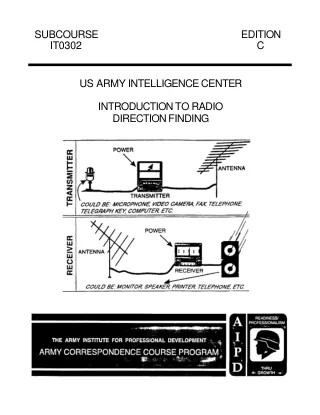 IT0302 ·Army ·1999
Introduction to Radio Direction Finding
TO RADIO DIRECTION FINDING Subcourse Number IT0302 EDITION C US ARMY INTELLIGENCE CENTER FORT HUACHUCA, AZ 85613-6000 5 CREDIT HOURS EDITION DATE: AUGUST 1999 SUBCOURSE OVERVIEW This subcourse is designed to teach you the basic concepts… FM 21-60 ·Army ·1987
Visual Signals
1-1. General Visual signals are any means of communication that require sight and can be used to transmit prearranged messages rapidly over short distances. This includes the devices and means used for the recognition and identification of… TM 11-2635 ·Army ·1945
Q-Meter, Boonton Type 160-A
HE Manual of Radio Frequency Measurements is writ- ten principally around the types 100-A and 160-A Q- Meters. The same general measurement technique described in the Manual is also applicable to the type 170-A. Special pre- cautions… TM 11-947 ·Army ·1944
Power Unit PE-210
WAR DEPARTMENT TECHNICAL MANUAL T M 11-047 POWER UNIT PE-210 WAR DEPARTMENT 29 AUGUST 1944 RESTRICTED. DISSEMINATION OF RESTRICTED MATTER. The information contained in restricted documents and the essential charac teristics of restricted… TM 11-338 ·Army ·1944
Telephone Central Office Set TC-10
Covers the description, installation, operation, and maintenance of Telephone Central Office Set TC-10, including Switchboard BD-110. TM 11-2206 ·Army ·1944
Telegraph Terminal Set AN/TCC-1, Telegraph Terminal TH-1/TCC-1, and Filter F-2/GG
This manual supersedes TM 11-2206, dated 26 June 1944, and 29 September 1944 SECTION DESCRIPTION 1. GENERAL. a. Telegraph Terminal TH-1/TCC-1 (figs. 1, 2, and 3) is designed to provide two-way voice-frequency carrier telegraph communica-… TM 11-2215 ·Army ·1951
Teletypewriters TT-5/FG and TT-6/FG (Teletype Model 15)
Teletype model 15 p is fixed station communication equipment. schange typewritten p sither typ rd. which i: sake ponents, thereby both The tabl nd cushion th TM 11-4047 ·Army ·1945
Radio Receiver BC-1005-A: Repair Instructions
Each half of a 120-cycle-per-second signal gen- erated by the two halves of a twin-triode square wave oscillator is rectified separately by each half of a twin-diode negative pulse rectifier. The negative pulses (a and b) of voltage are… TM 11-6720 ·Army ·1971
Direct Support, General Support, and Depot Maintenance Manual: Photographic Surveillance System, Airborne KS-113A
TM 11-6720-—250-35 quired to apply the vertical, right oblique or left oblique light sensor (Unit 5) exposure (bright- ness) signal through the photo junction panel (Unit 8) to the camera (Unit 9). This exposure (brightness) signal drives… FM 11-43 ·Army ·1995
The Signal Leader's Guide
Successfully supporting the commander with reliable and redundant communications is a direct result of detailed planning. Planning signal support operations should not occur in a vacuum or just among signalers. For communications to… TM 11-5985-357-13 ·Army ·1991
Antenna Group OE-254/GRC
Section I. GENERAL 1-1. Scope a. This manual describes Antenna Group OE-254/GRC (fig. 1-1) and provides instruction for installation, operation, and maintenance. It includes instructions for operation under usual and unusual conditions,… TM 11-998 ·Army ·1949
Power Unit PE-220-C
This unit generates a high voltage which is dangerous to life. The operator must be careful and observe every safety regulation at all times. Keep clear of all live parts. Never make connection while the unit is in operation. Severe and… TM 11-2223 ·Army ·1947
Typing and Nontyping Reperforators, Teletype Model 14
Section I. DESCRIPTION I. General a. Teletype model 14 typing reperforator is a motor-driven device for receiving and, when equipped with a keyboard base, transmitting messages in the form of electrical impulses and recording the messages… TM 11-408 ·Army ·1944