

 TM 11-642 ·Army ·1952
Radio Sets AN/VRC-20, AN/VRC-21, and AN/VRC-22
C 1, TM 11-642 . TO 16-30VRC20-5 DEPARTMENT OF THE ARMY TECHNICAL MANUAL DEPARTMENT OF THE AIR FORCE TECHNICAL ORDER RADIO SETS AN/VRC-20, AN/VRC-21, AND AN/VRC-22 C 1, TM 11-642 TO 16-80VRC20-5 TM 11-642/TO 16-30VRC20-5, 11 July 1952, is… TM 11-647 ·Army ·1955
Radio Receiving Set AN/FRR-38
5. System Application a. The receiving set is the radio receiving link in a radioteletype communications system. The rela- tionship of the receiving set to other equipments that are required to form a space diversity radio- teletype… TM 11-655 ·Army ·1954
Fundamentals of Telegraphy (Teletypewriter)
Section I . DEVELOPMENT AND DESCRIPTION 1. General Early methods of communication seem prim itive when compared with present day systems. These early methods included signaling audibly by gunfire, drums, and other loud noises, and visually… TM 11-661 ·Army ·Undated
Electrical Fundamentals: Direct Current
Google This is a digital copy of a book that was preserved for generations on library shelves before it was carefully scanned by Google as part of a project to make the world's books discoverable online. It has survived long enough for the… TM 11-662 ·Army ·1955
Basic Theory and Application of Electron Tubes
a. The success of modern military operations, as well as of the peacetime activities of the armed forces, depends in a great measure on signal communication facilities. Whether on the offense or the defense, in the front lines or far… TM 11-6625 ·Army ·1964
Direct Support and General Support Maintenance Manual: Wattmeter ME-82/U
TM 11-6625-595-34 Section I. GENERAL 1-1. Scope This manual covers direct and general support maintenance for Wattmeter ME-82/U (fig. 1-1). It includes instructions for troubleshooting, testing, and repairing of the ME82/U, and replacing… TM 11-6625-202 ·Army ·1958
Test Sets I-181, I-181-A, and I-181-B
6. Description (fig. 1) The test set meter and controls are assembled on a panel within a metal case. The case is equipped with cushioned feet, a carrying handle, and a removable cover that is secured by latches. Four single-conductor and… TM 11-6625-203-12 ·Army ·1959
Multimeter AN/URM-105, Including Multimeter ME-77/U
5. Components of Multimeter AN/URM-—105 (fig. 1) Quantity Item Height (in.) Depth (in.) Width (in.) Re Multimeter: MEe07/U 2) 20 re ee ee 6% 4 3% 2 2 Alligator clips (1 red, 1 black). 2 Electrical clips.(1 red, 1 black). 6. Description a.… TM 11-6625-261-12 ·Army ·1961
Operator's and Organizational Maintenance Manual: Audio Oscillators TS-382A/U through TS-382F/U
Be careful when working on the 450-volt plate and power supply circuits, or on the 115-volt ac line connections. Dangerous voltages exist at these points. DON'T TAKE CHANCES! TM 11-6625-274 ·Army ·1960
Test Sets, Electron Tube TV-7/U, TV-7A/U, TV-7B/U, and TV-7D/U
Field and depot maintenance manual for Electron Tube Test Sets TV-7/U, TV-7A/U, TV-7B/U, and TV-7D/U, covering theory of operation, troubleshooting, repair, and alignment. TM 11-6625-274-12 ·Army ·1960
Test Sets, Electron Tube TV-7/U, TV-7A/U, TV-7B/U, and TV-7D/U
Be careful not to contact high-voltage connections or the 115-volt ac input connections when replacing tubes in the test set. Voltages up to 300 volts ac may be encountered in this equipment. Serious injury or death may result from contact… TM 11-6625-299-15 ·Army ·1954
Signal Generators AN/URM-64 and AN/URM-64A
Section Paragraphs 6.-7.b. 6. GENERAL ELECTRICAL CHARACTERISTICS. a. POWER REQUIREMENTS. — Signal Generator TS-419/U is designed to operate from an external voltage source of 115 volts, +10 per cent, a-c, 50 to 1600 cycles per second,… TM 11-6625-3015-14 ·Army ·1988
Radio Test Set AN/PRM-34
Section I. GENERAL INFORMATION 1-1. MULTIPLE CONFIGURATION COVERAGE. MThis technical manual covers two basic configurations of Radio Test Set AN/PRM-34. The first includes serial numbers 1 through 634, and the second includes serial… TM 11-665 ·Army ·1952
C-W and A-M Radio Transmitters and Receivers
Google This is a digital copy of a book that was preserved for generations on library shelves before it was carefully scanned by Google as part of a project to make the world's books discoverable online. It has survived long enough for the… TM 11-666 ·Army ·1953
Antennas and Radio Propagation
Section THE ELECTROMAGNETIC WAVE 1. General a. The study of antennas and wave propazation is essential to a complete understanding radio communication, radar, loran, and other e:ectronic systems. In such systems, energy in the form of… TM 11-6660 ·Army ·1980
Organizational, DS, and GS Maintenance Manual: Meteorological Data Processing Groups OL-192/GMD-1 and OL-192A/GMD-1
This manual has been prepared to assist the user in operating, installing and maintaining the following REMEX reader/perforators: RAB612X (Figure 1-1, RAR612X (Figure 1-2), and RAF6120(Figure 1-3). All units punch tape at 120… TM 11-6660-204-10 ·Army ·1983
Hand Receipt for Radiosonde Recorders AN/TMQ-5, AN/TMQ-5A, AN/TMQ-5B, and AN/TMQ-5C
h. Quantity. Quantity of the end item covered by this hand receipt. i. Stock Number (Column a). National stock number of the item described. Items without stock numbers should be requisitioned by Federal Sup- ply Code for Manufacturers… TM 11-6660-206 ·Army ·1983
Hand Receipt Covering COEI, BII, and AAL for Rawin Sets AN/GMD-1A, AN/GMD-1B, AN/GMD-1C, and AN/GMD-1D
1. Scope This publication provides an overprinted DA Form 2062 (Hand Receipt) which lists the contents of Components of End Item (COEI), Basic Issue Items (BII), and Additional Authorization List (AAL) items related to Rawin Set AN/GMD-1A,… TM 11-6660-218-12 ·Army ·1967
Operator's and Organizational Maintenance Manual: Meteorological Station, Manual AN/TMQ-4
Section I. 1-1. Scope a. This manual describes Meteorological Station, Manual AN/TMQ-4, and covers its installation, operation, and maintenance. It includes operation, cleaning and inspection of equipment, and replacement of parts. b. The… TM 11-6665-209-20 ·Army ·1981
Organizational Maintenance Manual: Radiac Sets AN/PDR-27J, AN/PDR-27L, and AN/PDR-27Q
Google This is a digital copy of a book that was preserved for generations on library shelves before it was carefully scanned by Google as part of a project to make the world's books discoverable online. It has survived long enough for the… TM 11-6720 ·Army ·1971
Direct Support, General Support, and Depot Maintenance Manual: Photographic Surveillance System, Airborne KS-113A
TM 11-6720-—250-35 quired to apply the vertical, right oblique or left oblique light sensor (Unit 5) exposure (bright- ness) signal through the photo junction panel (Unit 8) to the camera (Unit 9). This exposure (brightness) signal drives… TM 11-680 ·Army ·1942
Teletypewriter Circuits and Equipment Fundamentals
This manual is a basic textbook covering the fundamentals of the circuits and equipment used in United States Army teletypewriter land-line and radio networks throughout the world. It may be used as a textbook or as a reference manual. It… TM 11-684 ·Army ·1961
Principles and Applications of Mathematics for Communications-Electronics
Google This is a digital copy of a book that was preserved for generations on library shelves before it was carefully scanned by Google as part of a project to make the world's books discoverable online. It has survived long enough for the… TM 11-685 ·Army ·1961
Fundamentals of Single-Sideband Communication
TO SINGLE-SIDEBAND COMMUNICATION Section GENERAL 1. Scope a. This manual covers the fundamental principles and theory involved in yvenerating, transmitting, and receiving single-sideband (ssb) signals. Single-sideband and…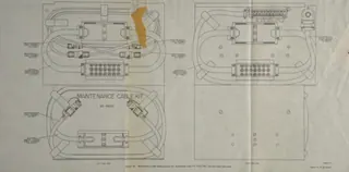 TM 11-687 ·Army ·Undated
TM 11-687/TO 31R2-2TRC24-11 Figures
 TM 11-689 ·Army ·1956
Radio Set AN/TRC-29 and Radio Repeater Set AN/TRC-39
Covers Radio Set AN/TRC-29 and Radio Repeater Set AN/TRC-39, including installation, adjustment, and operation of the radio relay system. TM 11-6940-205-15 ·Army ·1960
Operator's, Organizational, Field and Depot Maintenance Manual: Trainer, Radar AN/ULT-T2
in the 7.36- to 10.0-kme frequency range. The horn antenna is fed by a section of waveguide with inside dimensions that are slightly smaller than the standard X-band waveguide. The waveguide is terminated at one end with a… TM 11-700 ·Army ·1942
Interphone Equipments RC-53 and RC-53-A
TM 11-700 RESTRICTED TECHNICAL MANUAL! WAR DEPARTMENT No. 11-700 J WASHINGTON, February 2, 1942. INTERPHONE EQUIPMENTS RC-53 AND RC-53-A Prepared under direction of the Chief Signal Officer Paragraphs SECTION I. Description . 1-5 II.… TM 11-702 ·Army ·1944
Interphone Equipment RC-99
Demolish all panels, castings, switch-and instrument-boards . 3. Destroy all controls, switches, relays, connecting means and meters. 4. Rip out all wiring in electrical equipment. Smash gas and oil lines, and water cooling systems in… TM 11-704 ·Army ·1951