

 TM 11-2650 ·Army ·1945
Modulator MD-69/FRT (Wilcox Electric Types 50A and 50A3)
TM 11-2650 C1 TECHNICAL MANUAL MODULATOR MD-69/FRT CHANGES No, 1 TM 11-2650, 19 November 1945, is changed as follows: Title is changed to read: Modulator MD-69/ FRT. 32. Relays (Superseded) a. The proper operation of the relays in the aux-… TM 11-2651 ·Army ·1961
Antenna Groups AN/GRA-4 and AN/GRA-12
1. General a. This section assigns maintenance functions and repair operations to be performed by the lowest appropriate maintenance echelon. b. The columns are as follows: (1) Part or component. This column shows only the nomenclature or… TM 11-2653 ·Army ·1945
Vacuum Tube Voltmeter, Precision Model EV-10-MCP
Pts eee nts yee fh Pe Oty Pyle ‘ this equipment for ee FANS 2: ; Smash—Use sledges, axes, handaxes, pickaxes, hammers, Burn—Use gasoline, kerosene, oil, flame throwers, incendiary grenades. . Explosives—Use firearms, grenades, TNT. .… TM 11-2654 ·Army ·1945
Vacuum Tube Voltmeter Hickok Model 110-B
Vacuum tube voltmeter (Hickok model 110-B) is an electronic test unit used to measure either d-c (direct-current) or a-c (alternatingcurrent) voltages. Readings are registered on a single meter which has five scales. The circuits are… TM 11-2669 ·Army ·1945
Keyer KY-7/FRT
SECTION I. DESCRIPTION 1. GENERAL. Keyer KY-7/FRT (fig. 1) is a unit designed to adapt any type of keyed radio transmitting equipment to tone-keying operation. The keyer is intended for use with a 500-ohm keying line. This line feeds a… TM 11-2671 ·Army ·1945
Radio Transmitters (Wilcox Electric Types 96A, 96C, and 96C3)
Covers the description, operation, and maintenance of Wilcox Electric Types 96A, 96C, and 96C3 radio transmitters. TM 11-2674 ·Army ·1945
Crystal Test Set TS-314/FSM-1 (Ray Jefferson Model AF-30)
SECTION I DESCRIPTION OF CRYSTAL TEST SET TS-314/FSM-l ' 1. GENERAL. Crystal Test Set TS-314/FSM-1 (Ray Jefferson Activity and Fre quency Test Unit AF-30) is an instrument designed for checking the activity and frequency of quartz crystals… TM 11-2678 ·Army ·1953
Pulse Generator AN/PPM-1
(WARNING) HIGH VOLTAGE is used in the operation of this equipment. DEATH ON CONTACT may result if personnel fail to observe safety precautions. Be careful not to contact high-voltage connections or 115-volt input con- nections when working… TM 11-272 ·Army ·1942
Radio Sets SCR-210-A, -B, -C, -D, -E, -F, -G, -H, and -J; and SCR-245-A Through -P
Covers Radio Sets SCR-210 and SCR-245 series, including description, employment, operation, and functioning of components. TM 11-273 ·Army ·1941
Radio Sets SCR-193-A, SCR-193-B, SCR-193-C, SCR-193-D, and SCR-193-E
TM 11-273 RADIO SETS SCR-193-A, ETC. 1-4 1. Purpose.— Radio sets SCE-193-A, SCR-193-B, SCR-193-C, SCR-193-D, and SCR-193-E are designed for installation in vehicles for the purpose of providing intervehicular communication whether the… TM 11-284 ·Army ·1954
Radio Sets AN/GRC-3, -4, -5, -6, -7, and -8
Covers AN/GRC-3 through AN/GRC-8 radio sets, which use Receiver-Transmitters RT-66/GRC, RT-67/GRC, and RT-68/GRC. TM 11-285 ·Army ·1951
Radio Set AN/VRC-7
In case of electric shock, shut off the high voltage at once and ground the circuits. If the high voltage cannot be turned off without .delay, free the victim from contact with the live conductor as promptly as possible. Avoid direct… TM 11-286 ·Army ·1951
Radio Sets AN/VRC-8, AN/VRC-9 and AN/VRC-10
Section I. GENERAL 1. Scope a. This technical manual contains instructions for the installation, operation, and organizational maintenance of Radio Sets AN/VRC-8, —9, and -10. The information is intended primarly for operators and…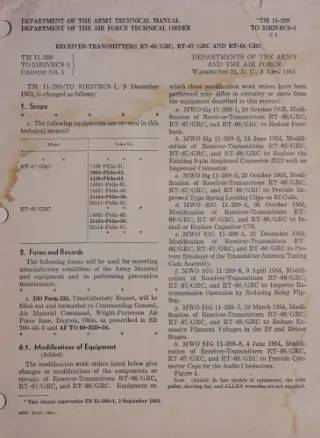 TM 11-289 ·Army ·1955
Receiver-Transmitters RT-66/GRC, RT-67/GRC and RT-68/GRC
Covers Receiver-Transmitters RT-66/GRC, RT-67/GRC, and RT-68/GRC, including operation, maintenance, and modification work orders. TM 11-291 ·Army ·1951
Radio Sets AN/VRC-13, AN/VRC-14, and AN/VRC-15
Section GENERAL 1. Scope a. This technical manual contains instructions for the installation, operation, and organizational maintenance of Radio Sets AN/VRC-13, -14, and -—15. The information is intended primarily for operators and… TM 11-295 ·Army ·1952
Radio Receiving Set AN/GRR-5
AGO 313A WARNING HIGH VOLTAGE is used in the operation of this equipment. DEATH ON CONTACT may result if personnel fail to observe safety precautions. TM 11-297 ·Army ·1955
Supplement to TM 11-297/ TO 16-30VRC19-5 Radio Sets AN/VRC-19, -19X, and -19Y
Supplement covering Radio Sets AN/VRC-19, -19X, and -19Y, with changes and supplementary information to the basic technical manual. TM 11-300 ·Army ·1944
Frequency Meter Sets SCR-211
To prevent the enemy from using or salvaging this equipment for his benefit. WHEN—When ordered by your commander. HOW — 1. Smash—Use sledges, axes, handaxes, pickaxes, hammers, crow- bars, heavy tools, etc. 2, Cut—Use axes, handaxes,… TM 11-302 ·Army ·1941
Charging Set SCR-169
TM: n-302 C 1 TECHNICAL MANUAL, 10y4. (Added.) Power units PE-HF-43 and PE-HG-43.— These units are identical with power units PE-HD—13 and PEHE-43. All information in paragraphs 1 to 10 inclusive pertaining to power units PE-HD-43 and… TM 11-303 ·Army ·1944
Test Sets I-56-C, -D, -H, -J
TM 11-303 Pars. 1-3 This manual supersedes War Department Training Circular 69, 19 May 1943 SECTION I DESCRIPTION 1. PURPOSE. Test Sets I-56-C, I-56-D, I-56-H and 1-56 J, referred to in this text as Test Set 1-56- (*), are electrical… TM 11-306 ·Army ·1943
Maintenance Equipments ME-13-A, B, C, and D
5. Adapter RS-259 This adapter is used for aligning Radio Sets SCR-509-(*), SCR-510- (*), and SCR-610-C*). It plugs into the transmitter Battery BA-39, thereby placing a 500-ohm, 5-watt resistance in series with the highvoltage (h-v) lead.… TM 11-307 ·Army ·1943
Signal Generators I-72-G and I-72-H
Covers the description, functioning, operation, and maintenance of Signal Generators I-72-G and I-72-H. TM 11-308 ·Army ·1944
Remote Control Unit RM-29-(*)
Covers the description, installation, operation, functioning, and maintenance of Remote Control Unit RM-29. TM 11-310 ·Army ·1943
Schematic Diagrams for Maintenance of Ground Radio Communication Sets
RESTRICTED TM 11-310 SCHEMATIC DIAGRAMS FOR MAINTENANCE OF GROUND RADIO COMMUNICATION SETS This manual contains a condensation of information for the maintenance of Signal Corps ground radio communication sets. It is presented as a… TM 11-312 ·Army ·1943
Remote Control Equipment RC-47-A, B, C, D, and G
C, nsny of itter ermit ote trol mitter e point pairs units, attery sed for m the he revers may switch. s th field es under r. The signating equipnd all equipM-13-(*) refers RM-13-D, and nd to those of the example, Control 55-D are comn —… TM 11-313 ·Army ·1943
Allen Model E-2 Unitron Rectifier
capture of this equipment, O PART OF IT CAN MY, BURN ALL cts are readily e, oil, paper, or tes and circuit ent-boards. means and meters. gas, oil, and water er rotating, moving phones, microainers, etc. or dispose of it in ULD NOT BE A-C… TM 11-317 ·Army ·1943
Signal Generator I-208
WAR DEPARTMENT Washington 25, D. C. 28 Aug 1943 This Technical Manual is furnished for the information and guidance of all concerned. RESTRICTED Dissemination of restricted matter.— The information con tained in restricted documents and… TM 11-318 ·Army ·1943
Alignment Equipment ME-73
Covers Alignment Equipment ME-73 and procedures for aligning Radio Sets SCR-509/510 and SCR-609/610 series. TM 11-321 ·Army ·1943
Test Set I-56-E
11-321 SIGNAL CORPS een nen rest aae Figure 1 View showing Test Set I-56-E complete with each unit in place in carrying case. TM 11-330 ·Army ·1944